PWM in Depth
Timer Operation
The timer plays a key role in PWM generation. It counts from zero to a specified maximum value (stored in a register), then resets and starts the cycle over. This counting process determines the duration of one complete cycle, called the period.
Compare Value
The timer’s hardware continuously compares its current count with a compare value (stored in a register). When the count is less than the compare value, the PWM signal stays HIGH; when the count exceeds the compare value, the signal goes LOW. By changing this compare value, you directly control the duty cycle.
PWM Resolution
Resolution refers to how precisely the duty cycle can be controlled. This is determined by the range of values the timer counts through in one complete cycle.
The timer counts from 0 to a maximum value based on the resolution. The higher the resolution, the more finely the duty cycle can be adjusted.
For a system with n bits of resolution, the timer counts from 0 to \(2^n - 1\), which gives \(2^n\) possible levels for the duty cycle.
For example:
- 8-bit resolution allows the timer to count from 0 to 255, providing 256 possible duty cycle levels.
- 10-bit resolution allows the timer to count from 0 to 1023, providing 1024 possible duty cycle levels.
Higher resolution gives more precise control over the duty cycle but requires the timer to count through more values within the same period. This creates a trade-off: to maintain the same frequency with higher resolution, you need a faster timer clock, or you must accept a lower frequency.
Simulation
You can modify the PWM resolution bits and duty cycle in this simulation. Adjusting the PWM resolution bits increases the maximum count but remains within the time period (it does not affect the duty cycle). Changing the duty cycle adjusts the on and off states accordingly, but it also stays within the period.
Relationship Between Duty Cycle, Frequency, and Resolution
This diagram shows how duty cycle, frequency, period, pulse width, and resolution work together in PWM generation. While it may seem a bit complex at first glance, breaking it down helps to clarify these concepts.
In this example, the timer resolution is 4 bits, meaning the timer counts from 0 to 15 (16 possible values). When the timer reaches its maximum value(i.e 15), an overflow interrupt is triggered (indicated by the blue arrow), and the counter resets to 0. The time it takes for the timer to count from 0 to its maximum value is called as “period”.
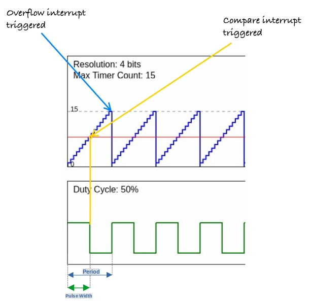
The duty cycle is configured to 50%, meaning the signal remains high for half the period. At each step in the counting process, the timer compares its current count with the duty cycle’s compare value. When the timer count exceeds this compare value (marked by the yellow arrow), the signal transitions from high to low. This triggers the compare interrupt, signaling the state change.
The time during which the signal is high is referred to as the pulse width.