Joystick Movement and Corresponding ADC Values
When you move the joystick along the X or Y axis, it produces an analog signal with a voltage that varies between 0 and 3.3 V (or 5 V if we connect it to 5 V supply). When the joystick is in its center (rest) position, the output voltage is approximately 1.65 V, which is half of the VCC (VCC is 3.3 V in our case).
Note
The reason it is 1.65 V in the center position is that the potentiometer acts as a voltage divider. When the potentiometer is moved, its resistance changes, causing the voltage divider to output a different voltage accordingly. Refer the voltate divider section.
The joystick has a total of 5 pins, and we will shortly discuss what each of them represents. Out of these, two pins are dedicated to sending the X and Y axis positions, which should be connected to the ADC pins of the microcontroller.
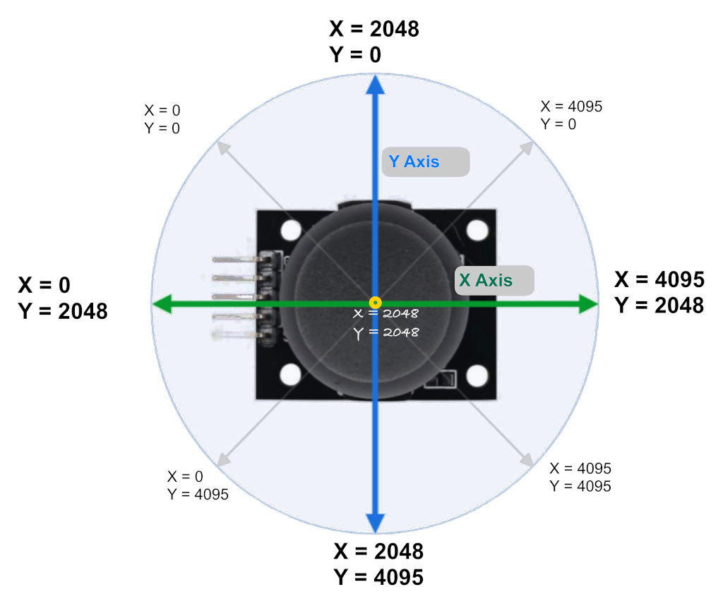
As you may already know, the Raspberry Pi Pico has a 12-bit SAR-type ADC, which converts analog signals (voltage differences) into digital values. Since it is a 12-bit ADC, the analog values will be represented as digital values ranging from 0 to 4095. If you’re not familiar with ADC, refer to the ADC section that we covered earlier.
Note:
The ADC values in the image are just approximations to give you an idea and won’t be exact. For example, I got around 1850 for X and Y at the center position. When I moved the knob toward the pinout side, X went to 0, and when I moved it to the opposite side, it went to 4095. The same applies to the Y axis.So, You might need to calibrate your joystick.