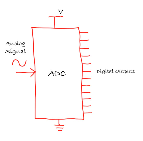
ADC (Analog to Digital Converter)
An Analog-to-Digital Converter (ADC) is a device used to convert analog signals (continuous signals like sound, light, or temperature) into digital signals (discrete values, typically represented as 1s and 0s). This conversion is necessary for digital systems like microcontrollers (e.g., Raspberry Pi, Arduino) to interact with the real world. For example, sensors that measure temperature or sound produce analog signals, which need to be converted into digital format for processing by digital devices.

ADC Resolution
The resolution of an ADC refers to how precisely the ADC can measure an analog signal. It is expressed in bits, and the higher the resolution, the more precise the measurements.
- 8-bit ADC produces digital values between 0 and 255.
- 10-bit ADC produces digital values between 0 and 1023.
- 12-bit ADC produces digital values between 0 and 4095.
The resolution of the ADC can be expressed as the following formula: \[ \text{Resolution} = \frac{\text{Vref}}{2^{\text{bits}} - 1} \]
Pico
Based on the Pico datasheet, Raspberry Pi Pico has 12-bit 500ksps Analogue to Digital Converter (ADC). So, it provides values ranging from 0 to 4095 (4096 possible values)
\[ \text{Resolution} = \frac{3.3V}{2^{12} - 1} = \frac{3.3V}{4095} \approx 0.000805 \text{V} \approx 0.8 \text{mV} \]
Pins
The Raspberry Pi Pico has four accessible ADC channels on the following GPIOs:
| GPIO Pin | ADC Channel | Function |
|---|---|---|
| GPIO26 | ADC0 | Can be used to read voltage from peripherals. |
| GPIO27 | ADC1 | Can be used to read voltage from peripherals. |
| GPIO28 | ADC2 | Can be used to read voltage from peripherals. |
| GPIO29 | ADC3 | Measures the VSYS supply voltage on the board. |
In pico, ADC operates with a reference voltage set by the supply voltage, which can be measured on pin 35 (ADC_VREF).
ADC Value and LDR Resistance in a Voltage Divider
In a voltage divider with an LDR and a fixed resistor, the output voltage \( V_{\text{out}} \) is given by:
\[ V_{\text{out}} = V_{\text{in}} \times \frac{R_{\text{LDR}}}{R_{\text{LDR}} + R_{\text{fixed}}} \]
It is same formula as explained in the previous chapter, just replaced the \({R_2}\) with \({R_{\text{LDR}}}\) and \({R_1}\) with \({R_{\text{fixed}}}\)
- Bright light (low LDR resistance): \( V_{\text{out}} \) decreases, resulting in a lower ADC value.
- Dim light (high LDR resistance): \( V_{\text{out}} \) increases, leading to a higher ADC value.
Example ADC value calculation:
Bright light:
Let's say the Resistence value of LDR is \(1k\Omega\) in the bright light (and we have \(10k\Omega\) fixed resistor).
\[ V_{\text{out}} = 3.3V \times \frac{1k\Omega}{1k\Omega + 10k\Omega} \approx 0.3V \]
The ADC value is calculated as: \[ \text{ADC value} = \left( \frac{V_{\text{out}}}{V_{\text{ref}}} \right) \times (2^{12} - 1) \approx \left( \frac{0.3}{3.3} \right) \times 4095 \approx 372 \]
Darkness:
Let's say the Resistence value of LDR is \(140k\Omega \) in very low light.
\[ V_{\text{out}} = 3.3V \times \frac{140k\Omega}{140k\Omega + 10k\Omega} \approx 3.08V \]
The ADC value is calculated as: \[ \text{ADC value} = \left( \frac{V_{\text{out}}}{V_{\text{ref}}} \right) \times (2^{12} - 1) \approx \left( \frac{3.08}{3.3} \right) \times 4095 = 3822 \]
Converting ADC value back to voltage:
Now, if we want to convert the ADC value back to the input voltage, we can multiply the ADC value by the resolution (0.8mV).
For example, let's take an ADC value of 3822:
\[ \text{Voltage} = 3822 \times 0.8mV = 3057.6mV \approx 3.06V \]