Servo Motors
Servo motors let you control position accurately. You might use them to point a camera, move parts of a small robot, or control switches automatically. They’re different from regular DC motors. Instead of spinning continuously, a servo moves to a specific angle and stays there.
In this chapter, we’ll make a servo sweep through three positions: 0°, 90°, and 180°.
Hardware Used
For this chapter, we will use the following components:
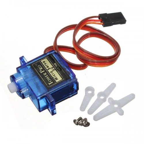
- SG90 Micro Servo Motor
- Jumper Wires:
- Female-to-Male(or Male to Male depending on how you are connecting) jumper wires for connecting the Pico 2 to the servo motor pins (Ground, Power, and Signal).
The SG90 is small, cheap, and easy to find. It is commonly used in learning projects and works well for demonstrations.
Servo Motor Basics
A typical hobby servo has three wires: Ground, Power, Signal. The power and ground wires supply energy to the motor. The signal wire is used to tell the servo which position to move to. The servo expects a PWM signal on this pin. Different pulse widths correspond to different angles.

You do not need to know the internal details to use a servo. You just need to generate the correct PWM signal.