Sending Joystick ADC Values to USB Serial (RP-HAL)
In the previous chapter, we used Embassy to read joystick ADC values and print them using logging. In the first version of this book, I was using RP-HAL while exploring and learning the ecosystem. I do not want to throw away that material, as it may still be useful for understanding older code or different approaches.
This chapter shows the same joystick ADC example implemented using RP-HAL and USB serial. If you are not interested in the RP-HAL version, you can skip this chapter.
Project from template
To set up the project, run:
cargo generate --git https://github.com/ImplFerris/pico2-template.git --tag v0.1.0
When prompted, give your project a name, like “joystick-usb” and select RP-HAL as the HAL.
Then, navigate into the project folder:
cd PROJECT_NAME
# For example, if you named your project "joystick-usb":
# cd joystick-usb
Additional Crates required
Update your Cargo.toml to add these additional crate along with the existing dependencies.
#![allow(unused)]
fn main() {
usb-device = "0.3.2"
usbd-serial = "0.2.2"
heapless = "0.8.0"

embedded_hal_0_2 = { package = "embedded-hal", version = "0.2.5", features = [
  "unproven",
] }
}
The first three should be familiar by now; they set up USB serial communication so we can send data between the Pico and the computer. heapless is a helper function for buffers.
embedded_hal_0_2 is the new crate. You might already have embedded-hal with version “1.0.0” in your Cargo.toml. So, you may wonder why we need this version. The reason is that Embedded HAL 1.0.0 doesn’t include an ADC trait to read ADC values, and the RP-HAL uses the one from version 0.2. (Don’t remove the existing embedded-hal 1.0.0; just add this one along with it.)
Additional imports
#![allow(unused)]
fn main() {
/// This trait is the interface to an ADC that is configured to read a specific channel at the time
/// of the request (in contrast to continuous asynchronous sampling).
use embedded_hal_0_2::adc::OneShot;

// for USB Serial
use usb_device::{class_prelude::*, prelude::*};
use usbd_serial::SerialPort;
use heapless::String;
}
USB Serial
Make sure you’ve completed the USB serial section and added the boilerplate code from there into your project.
#![allow(unused)]
fn main() {
    let usb_bus = UsbBusAllocator::new(hal::usb::UsbBus::new(
        pac.USB,
        pac.USB_DPRAM,
        clocks.usb_clock,
        true,
        &mut pac.RESETS,
    ));

    let mut serial = SerialPort::new(&usb_bus);

    let mut usb_dev = UsbDeviceBuilder::new(&usb_bus, UsbVidPid(0x16c0, 0x27dd))
        .strings(&[StringDescriptors::default()
            .manufacturer("implRust")
            .product("Ferris")
            .serial_number("12345678")])
        .unwrap()
        .device_class(2) // 2 for the CDC, from: https://www.usb.org/defined-class-codes
        .build();

    let mut buff: String<64> = String::new();
}
ADC and Pin Setup
The joystick wiring is the same as before. GPIO 27 and GPIO 26 are connected to the VRX and VRY pins of the joystick and are configured as ADC inputs. GPIO 15 is used for the joystick button with an internal pull-up.
#![allow(unused)]
fn main() {
let mut adc = hal::Adc::new(pac.ADC, &mut pac.RESETS);

//VRX Pin
let mut adc_pin_1 = hal::adc::AdcPin::new(pins.gpio27).unwrap();
// VRY pin
let mut adc_pin_0 = hal::adc::AdcPin::new(pins.gpio26).unwrap();

let mut btn = pins.gpio15.into_pull_up_input();
}
Printing Co-ordinates
Just like in the Embassy version, we avoid printing ADC values continuously. We track the previous readings and only print when the change crosses a threshold. The same approach is used for the button. We detect a press by checking for a state transition, so the message is printed only once per press.
#![allow(unused)]
fn main() {
let mut prev_vrx: u16 = 0;
let mut prev_vry: u16 = 0;
let mut print_vals = true;
}
Reading ADC Values:
First, read the ADC values for vrx and vry. If there’s an error during the read operation, we ignore it and continue the loop:
#![allow(unused)]
fn main() {
let Ok(vry): Result<u16, _> = adc.read(&mut adc_pin_0) else {
    continue;
};
let Ok(vrx): Result<u16, _> = adc.read(&mut adc_pin_1) else {
    continue;
};
}
Checking for Threshold Changes:
Next, we check if the absolute difference between the current and previous values of vrx or vry exceeds a threshold (e.g., 100). If so, we update the previous values and set the print_vals flag to true:
#![allow(unused)]
fn main() {
if vrx.abs_diff(prev_vrx) > 100 {
    prev_vrx = vrx;
    print_vals = true;
}

if vry.abs_diff(prev_vry) > 100 {
    prev_vry = vry;
    print_vals = true;
}
}
Using a threshold filters out small ADC fluctuations, avoids unnecessary prints, and ensures updates only for significant changes.
Printing the Coordinates
If print_vals is true, we reset it to false and print the X and Y coordinates via the USB serial:
#![allow(unused)]
fn main() {
if print_vals {
    print_vals = false;

    buff.clear();
    write!(buff, "X: {} Y: {}\r\n", vrx, vry).unwrap();
    let _ = serial.write(buff.as_bytes());
}
}
Button Press Detection with State Transition
The button is normally in a high state. When you press the knob button, it switches from high to low. However, since the program runs in a loop, simply checking if the button is low could lead to multiple detections of the press. To avoid this, we only register the press once by detecting a high-to-low transition, which indicates that the button has been pressed.
To achieve this, we track the previous state of the button and compare it with the current state before printing the “button pressed” message. If the button is currently in a low state (pressed) and the previous state was high (not pressed), we recognize it as a new press and print the message. Then, we update the previous state to the current state, ensuring the correct detection of future transitions.
#![allow(unused)]
fn main() {
let btn_state = btn.is_low().unwrap();
if btn_state && !prev_btn_state {
    let _ = serial.write("Button Pressed\r\n".as_bytes());
    print_vals = true;
}
prev_btn_state = btn_state;
}
The Full code
#![no_std]
#![no_main]

use core::fmt::Write;
use embedded_hal::{delay::DelayNs, digital::InputPin};
use embedded_hal_0_2::adc::OneShot;
use hal::block::ImageDef;
use heapless::String;
use panic_halt as _;
use rp235x_hal as hal;

use usb_device::{class_prelude::*, prelude::*};
use usbd_serial::SerialPort;

#[link_section = ".start_block"]
#[used]
pub static IMAGE_DEF: ImageDef = hal::block::ImageDef::secure_exe();

const XTAL_FREQ_HZ: u32 = 12_000_000u32;

#[hal::entry]
fn main() -> ! {
    let mut pac = hal::pac::Peripherals::take().unwrap();
    let mut watchdog = hal::Watchdog::new(pac.WATCHDOG);

    let clocks = hal::clocks::init_clocks_and_plls(
        XTAL_FREQ_HZ,
        pac.XOSC,
        pac.CLOCKS,
        pac.PLL_SYS,
        pac.PLL_USB,
        &mut pac.RESETS,
        &mut watchdog,
    )
    .ok()
    .unwrap();
    let mut timer = hal::Timer::new_timer0(pac.TIMER0, &mut pac.RESETS, &clocks);

    let sio = hal::Sio::new(pac.SIO);
    let pins = hal::gpio::Pins::new(
        pac.IO_BANK0,
        pac.PADS_BANK0,
        sio.gpio_bank0,
        &mut pac.RESETS,
    );
    // let mut led = pins.gpio25.into_push_pull_output();

    let usb_bus = UsbBusAllocator::new(hal::usb::UsbBus::new(
        pac.USB,
        pac.USB_DPRAM,
        clocks.usb_clock,
        true,
        &mut pac.RESETS,
    ));

    let mut serial = SerialPort::new(&usb_bus);

    let mut usb_dev = UsbDeviceBuilder::new(&usb_bus, UsbVidPid(0x16c0, 0x27dd))
        .strings(&[StringDescriptors::default()
            .manufacturer("implRust")
            .product("Ferris")
            .serial_number("12345678")])
        .unwrap()
        .device_class(2) // 2 for the CDC, from: https://www.usb.org/defined-class-codes
        .build();

    let mut btn = pins.gpio15.into_pull_up_input();

    let mut adc = hal::Adc::new(pac.ADC, &mut pac.RESETS);

    //VRX Pin
    let mut adc_pin_1 = hal::adc::AdcPin::new(pins.gpio27).unwrap();
    // VRY pin
    let mut adc_pin_0 = hal::adc::AdcPin::new(pins.gpio26).unwrap();

    let mut prev_vrx: u16 = 0;
    let mut prev_vry: u16 = 0;
    let mut prev_btn_state = false;
    let mut buff: String<64> = String::new();
    let mut print_vals = true;
    loop {
        let _ = usb_dev.poll(&mut [&mut serial]);

        let Ok(vry): Result<u16, _> = adc.read(&mut adc_pin_0) else {
            continue;
        };
        let Ok(vrx): Result<u16, _> = adc.read(&mut adc_pin_1) else {
            continue;
        };

        if vrx.abs_diff(prev_vrx) > 100 {
            prev_vrx = vrx;
            print_vals = true;
        }

        if vry.abs_diff(prev_vry) > 100 {
            prev_vry = vry;
            print_vals = true;
        }

        let btn_state = btn.is_low().unwrap();
        if btn_state && !prev_btn_state {
            let _ = serial.write("Button Pressed\r\n".as_bytes());
            print_vals = true;
        }
        prev_btn_state = btn_state;

        if print_vals {
            print_vals = false;

            buff.clear();
            write!(buff, "X: {} Y: {}\r\n", vrx, vry).unwrap();
            let _ = serial.write(buff.as_bytes());
        }

        timer.delay_ms(50);
    }
}

#[link_section = ".bi_entries"]
#[used]
pub static PICOTOOL_ENTRIES: [hal::binary_info::EntryAddr; 5] = [
    hal::binary_info::rp_cargo_bin_name!(),
    hal::binary_info::rp_cargo_version!(),
    hal::binary_info::rp_program_description!(c"JoyStick USB"),
    hal::binary_info::rp_cargo_homepage_url!(),
    hal::binary_info::rp_program_build_attribute!(),
];
Clone the existing project
You can clone (or refer) project I created and navigate to the joystick-usb folder.
git clone https://github.com/ImplFerris/pico2-rp-projects
cd pico2-projects/joystick-usb/
How to Run?
The method to flash (run the code) on the Pico is the same as usual. However, we need to set up tio to interact with the Pico through the serial port (/dev/ttyACM0). This allows us to read data from the Pico or send data to it.
tio
Make sure you have tio installed on your system. If not, you can install it using:
apt install tio
Connecting to the Serial Port
Run the following command to connect to the Pico’s serial port:
tio /dev/ttyACM0
This will open a terminal session for communicating with the Pico.
Flashing and Running the Code
Open another terminal, navigate to the project folder, and flash the code onto the Pico as usual:
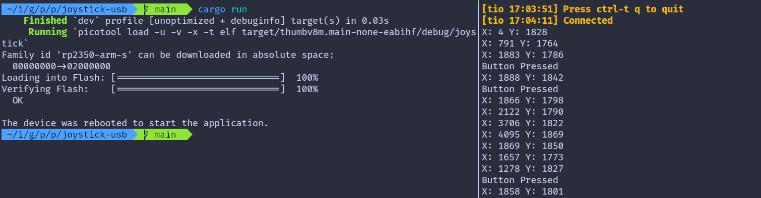
cargo run
If everything is set up correctly, you should see a “Connected” message in the tio terminal. As you move the joystick, the coordinates will be printed. Pressing the knob downwards will also display a “Button pressed” message.