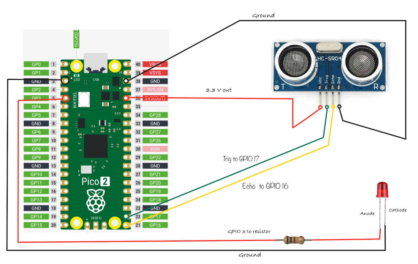
Circuit for HC-SR04+
Skip this step if you are using the 5 V-only variant of the HC-SR04.
Connection for the Pico and Ultrasonic:
| Pico Pin | Wire | HC-SR04+ Pin |
|---|---|---|
| 3.3 V |
|
VCC |
| GPIO 17 |
|
Trig |
| GPIO 16 |
|
Echo |
| GND |
|
GND |
- VCC: Connect the VCC pin on the HC-SR04+ to the 3.3 V pin on the Pico.
- Trig: Connect to GPIO 17 on the Pico to start the ultrasonic sound pulses.
- Echo: Connect to GPIO 16 on the Pico; this pin sends a pulse when it detects the reflected signal, and the pulse length shows how long the signal took to return.
- GND: Connect to the ground pin on the Pico.
- LED: Connect the anode (long leg) of the LED to GPIO 3.
Connection for the Pico and LED:
| Pico Pin | Wire | Component |
|---|---|---|
| GPIO 3 |
|
Resistor |
| Resistor |
|
Anode (long leg) of LED |
| GND |
|
Cathode (short leg) of LED |