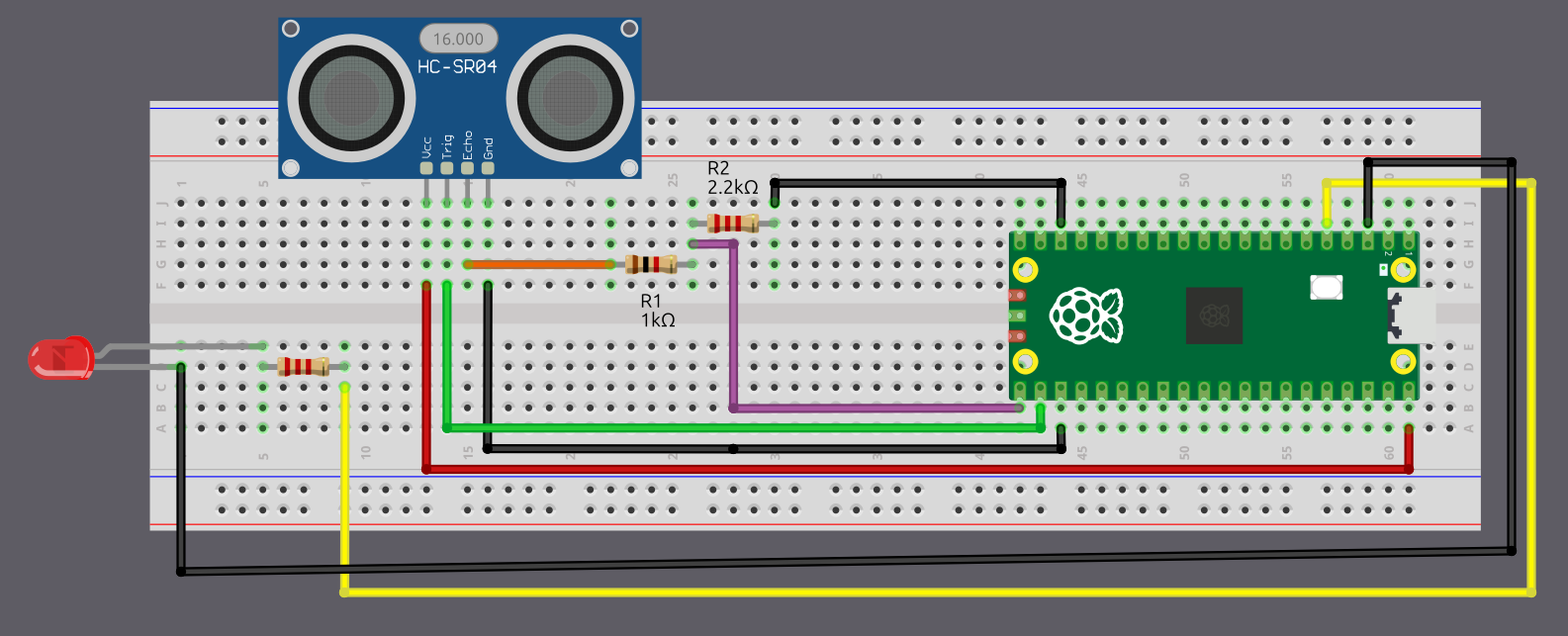
Wiring the HC-SR04 to the Pico 2 Using a Voltage Divider
If you are using the regular HC-SR04 like I am, you will need to create a voltage divider for the Echo pin. In this section we will look at how to set up the circuit. However, if you are lucky and you bought the HC-SR04 Plus, you can skip to the next page. The circuit becomes much simpler because you can power the sensor with 3.3 V instead of 5 V.
Common resistor combination
Below are some resistor pairs you can use to bring the HC-SR04 Echo signal down to about 3.3 V. R1 is the resistor connected to the Echo pin, and R2 is the resistor connected to ground.
| R1 (With Echo) | R2 (With Gnd) | Output Voltage |
|---|---|---|
| 330 Ω | 470 Ω | 2.94 V |
| 330 Ω | 680 Ω | 3.37 V |
| 470 Ω | 680 Ω | 2.96 V |
| 680 Ω | 1 kΩ | 2.98 V |
| 1 kΩ | 1.8 kΩ | 3.21 V |
| 1 kΩ | 2 kΩ | 3.33 V |
| 1 kΩ | 2.2 kΩ | 3.44 V |
| 1.5 kΩ | 2.2 kΩ | 2.97 V |
| 2.2 kΩ | 3.3 kΩ | 3.00 V |
| 3.3 kΩ | 4.7 kΩ | 2.94 V |
| 4.7 kΩ | 6.8 kΩ | 2.96 V |
| 6.8 kΩ | 10 kΩ | 2.98 V |
| 22 kΩ | 33 kΩ | 3.00 V |
| 33 kΩ | 47 kΩ | 2.94 V |
| 47 kΩ | 68 kΩ | 2.96 V |
You can choose any resistor pair from the table because all of them bring the 5 V Echo signal down to a safe level near 3.3 V. In practice it is best to use the values you already have in your kit.r
Connection for the Raspberry Pi Pico 2 and Ultrasonic Sensor
| Pico 2 Pin | Wire | HC-SR04 Pin |
|---|---|---|
| VBUS (Pin 40) |
|
VCC |
| GPIO 17 |
|
Trig |
| GPIO 16 (via Voltage Divider) |
|
Echo (through 1 kΩ/2.2 kΩ divider) |
| GND |
|
GND |
- VCC: Connect the VCC pin on the HC-SR04 to VBUS (Pin 40) on the Pico 2. The HC-SR04 requires 5 V power, and VBUS provides 5 V from the USB connection.
- Trig: Connect to GPIO 17 on the Pico 2 to trigger the ultrasonic sound pulses.
- Echo: Connect to GPIO 16 on the Pico 2 through a voltage divider (1 kΩ resistor from Echo pin, 2 kΩ or 2.2 kΩ resistor to ground). The junction between the resistors connects to GPIO 16. This divider steps down the 5 V Echo signal to ~3.4 V, protecting the Pico’s 3.3 V GPIO pins.
- GND: Connect to any ground pin on the Pico 2.
Connection for the Pico 2 and LED
| Pico 2 Pin | Wire | Component |
|---|---|---|
| GPIO 3 |
|
Resistor (220 Ω-330 Ω) |
| Resistor |
|
Anode (long leg) of LED |
| GND |
|
Cathode (short leg) of LED |